Pulse Code Modulation (PCM) Study Guide
Introduction to PCM
Pulse Code Modulation (PCM) is a digital representation of an analog signal where the magnitude of the signal is sampled regularly at uniform intervals, then quantized to a series of symbols in a digital (usually binary) code.
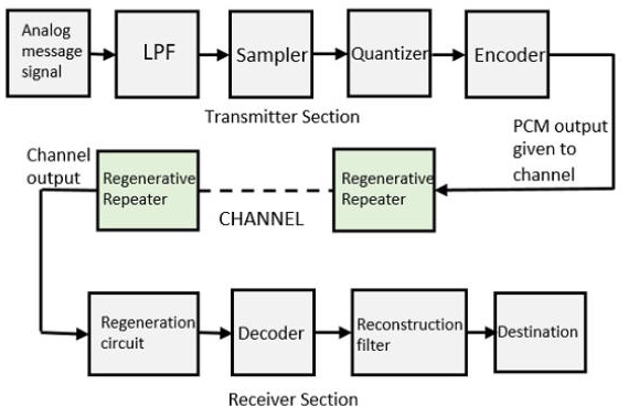
Figure 1. Block
diagram of a basic PCM system
Key Concept: PCM is the standard form of digital audio in computers, compact discs, digital telephony, and other digital audio applications.
PCM was invented in 1937 by Alec Reeves at the International Telephone and Telegraph.
The technology to implement it practically wasn't available until the
development of semiconductor components which started in 1948. The first
successful commercial PCM telecommunication system was developed at Bell
Labs and put into operation in 1962. This system, known as T1, utilized
24 digital channels and was a significant advancement in
telecommunications, enabling greater capacity through digitization and
time-division multiplexing.
The PCM Transmiter
PCM transmitter involves four main steps:
- Low-pass filter limits signal bandwidth,
preventing aliasing during sampling.
- Sampling: Converting a continuous-time signal into a discrete-time signal
- Quantization: Converting a continuous-amplitude signal into a discrete-amplitude signal
- Encoding: Representing each quantized sample by a binary code
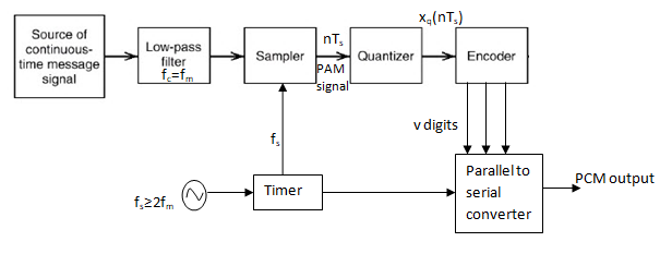
1. Sampling
Low Pass Filter eliminates the high frequency
components present in the input analog signal which is greater than the
highest frequency of the message signal, to avoid aliasing of the
message signal.
Sampling converts a continuous-time signal into a discrete-time signal by measuring the signal's amplitude at regular time intervals.
Nyquist Theorem
The sampling theorem states that a signal can be exactly reconstructed if the sampling frequency is greater than twice the highest frequency component in the signal.
fs > 2 × fmax
Where:
- fs = Sampling frequency
- fmax = Highest frequency in the input signal
Example: For audio signals with a maximum frequency of 20 kHz, the sampling rate should be at least 40 kHz. CD-quality audio uses 44.1 kHz.
2. Quantization
Quantization converts the continuous-amplitude samples into discrete amplitude values.
Quantization Levels
The number of possible amplitude values is determined by the number of bits used:
Number of levels = 2n
Where n = number of bits per sample
| Bits per sample |
Quantization levels |
Application |
| 8-bit |
256 |
Telephone quality |
| 16-bit |
65,536 |
CD audio |
| 24-bit |
16,777,216 |
Professional audio |
Quantization Error
The difference between the actual analog value and the quantized digital value is called quantization error or quantization noise.
Signal-to-Quantization-Noise Ratio (SQNR) = 6.02n + 1.76 dB
3. Encoding
Each quantized sample is converted to a binary code. The most common encoding method is linear PCM where the quantization levels are uniformly spaced.
Binary Representation
For a 3-bit system (8 levels):
| Quantization Level |
Binary Code |
| 0 |
000 |
| 1 |
001 |
| 2 |
010 |
| ... |
... |
| 7 |
111 |
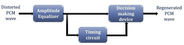
PCM REGENERATIVE REPEATER
A PCM regenerative repeater reconstructs and retransmits digital
signals. It compensates for signal degradation caused by the
transmission medium, ensuring reliable data transmission over longer
distances. These repeaters perform equalization, timing recovery, and
decision-making to regenerate the original signal.
A PCM repeater
essentially performs three key operations:
1. Reshaping: It
reconstructs the distorted pulses, restoring their original shape.
2. Retiming: It corrects the timing of the pulses,
ensuring they are aligned with the original clock signal. To regenerate
the signal accurately, the repeater needs a timing signal. This timing
signal is typically extracted from the received PCM pulses themselves.
3. Amplification: It increases the signal strength
to compensate for signal loss.
Modern PCM repeaters can be implemented as single integrated circuits
(ICs), which offer advantages in terms of performance, power
consumption, and reliability.
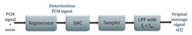
PCM RECEIVER
The PCM receiver consists of three main parts:
1. Regenerator: A regenerative repeater is placed at
the receiving end also so as to have an exact PCM transmitted signal.
Here, also the regenerator works in a similar manner as that when
employed in the transmission path. It eliminates the channel induced
noise and reshapes the pulse.
2. DAC and Sampler: Digital to analog converter
performs the conversion of digital signal again into its analog form by
making use of the sampler. As the actual message signal was analog thus
at the receiver end there is a necessity to again convert it into its
original form.
3. LPF: The sampler generates analog signal but that
is not the original message signal. Thus, the output of the sampler is
fed to the LPF having cutoff frequency fm. This is sometimes termed as
the reconstruction filter that produces the original message signal.
Advantages of PCM
- Noise immunity: Digital signals are less susceptible to noise and interference
- Regeneration: Digital signals can be regenerated without degradation
- Flexibility: Easy to multiplex and process digitally
- Security: Easier to encrypt digital signals
- Storage: Digital data is easier to store and retrieve
Disadvantages of PCM
- Bandwidth: Requires larger bandwidth than analog transmission
- Complexity: Requires complex encoding and decoding circuitry
- Quantization noise: Introduces quantization error
Applications of PCM
- Digital audio (CDs, DVDs, digital telephony)
- Digital telephony (standard for digital voice transmission)
- Computer audio interfaces
- Digital video
- Medical imaging
PCM Variations
Differential PCM (DPCM)
Encodes the difference between the current sample and a predicted value from previous samples.
Adaptive DPCM (ADPCM)
Varies the size of the quantization step to allow better reproduction of signals with varying amplitude.
Bit Rate Calculation
The bit rate of a PCM system is calculated as:
Bit rate = Sampling rate × Number of bits per sample × Number of channels
Example: CD-quality audio has:
- Sampling rate: 44.1 kHz
- Bits per sample: 16
- Channels: 2 (stereo)
Bit rate = 44,100 × 16 × 2 = 1,411,200 bits/sec (1.411 Mbps)
Self-Assessment Quiz
1. What is the minimum sampling rate required for a signal with maximum frequency of 15 kHz?
Answer: According to Nyquist theorem, it should be greater than 30 kHz (2 × 15 kHz).
2. How many quantization levels are there in a 12-bit PCM system?
Answer: 212 = 4,096 levels.
3. Calculate the SQNR for a 16-bit PCM system.
Answer: 6.02 × 16 + 1.76 = 98.08 dB.
4. What is the bit rate of a mono PCM system with 8 kHz sampling rate and 8 bits per sample?
Answer: 8,000 × 8 × 1 = 64,000 bits/sec (64 kbps).
5. Name two advantages of PCM over analog transmission.
Answer: Any two from: noise immunity, regeneration capability, flexibility, security, easier storage.